Schematik build
How to Build an RFID Treasure Chest with ESP32
Tap the right NFC tag to unlock a servo latch with dramatic effects
Schematik
Published April 9, 2026 · Updated June 12, 2026
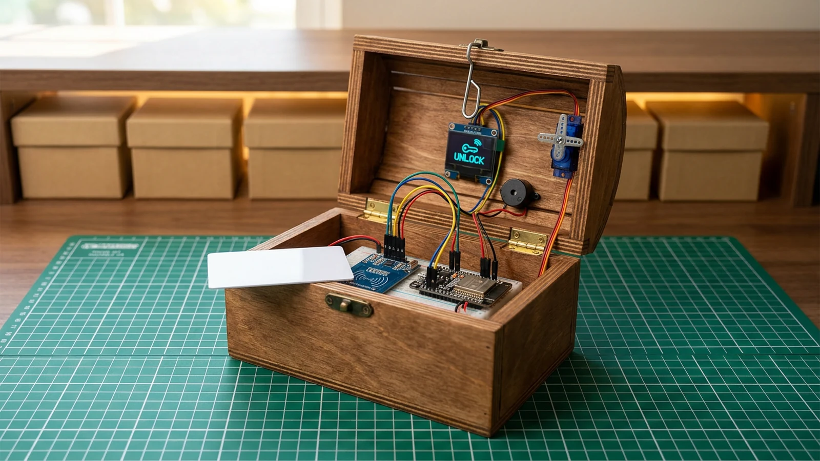
What you'll build
This guide builds an RFID-locked treasure chest using an ESP32, an MFRC522 reader, an SG90 servo as the latch, a piezo buzzer for audio feedback, and an SSD1306 OLED for status text. Tapping an authorised tag triggers a three-note unlock fanfare and swings the servo to the open position. An unrecognised tag plays a descending denied buzz and shows "DENIED" on the display. The chest auto-locks after a configurable timeout.
The project covers SPI communication with the MFRC522, reading MIFARE tag UIDs, comparing them against a stored value in the sketch, driving a servo with precise angle commands, and I2C communication with the OLED. It is a self-contained build: one valid UID hard-coded in validUid, one servo, and one display.
What you are building
The firmware has five jobs:
- initialise the MFRC522 over SPI (
SS_PINGPIO 5,RST_PINGPIO 27) and check for new cards each loop, - compare each presented tag's UID against the four-byte
validUidarray, - if valid, call
unlockChest()— servo to 90°, play the granted tune, display "UNLOCKED!", recordopenedAtMs, - if invalid, call
lockChest()— servo to 0°, play the denied buzz, display "DENIED", - auto-lock after
AUTO_LOCK_MSmilliseconds (default8000) by checking elapsed time inloop().
Enrolling multiple UIDs, storing them in NVS, or adding a master-card mode are left as extensions.
Upload and calibrate
Flash the sketch from Schematik and open Serial Monitor at 115200 baud. On first boot you will see:
Treasure Chest ready
Tap any tag — the UID prints:
Tag UID: DE:AD:BE:EF
Copy those four hex bytes into the validUid array in the sketch, reflash, and tap the same tag. The OLED should show "UNLOCKED!" and the servo should swing to 90°. After AUTO_LOCK_MS milliseconds (8 seconds by default) it returns to 0° and Serial Monitor shows "Auto-locked".
To change the auto-lock delay, adjust:
const unsigned long AUTO_LOCK_MS = 8000;
The validUid array holds exactly four bytes. If your tag prints more than four bytes, use only the first four.
Troubleshooting
- Serial Monitor shows no UID when a tag is presented. Check MOSI (GPIO 23), MISO (GPIO 19), SCK (GPIO 18), SS (GPIO 5), and RST (GPIO 27). A single incorrect connection silences the MFRC522 entirely. Confirm the module is powered from 3.3 V, not 5 V.
- OLED is blank or shows garbled pixels. The I2C address is assumed to be
0x3C. If your module uses0x3D, change the address indisplay.begin(SSD1306_SWITCHCAPVCC, 0x3C). Also check that SDA and SCL are not swapped. - Servo twitches but does not move to 90°. The servo is likely drawing more current than the USB port can supply cleanly. Power the servo 5 V rail from a dedicated source and ensure the ground is shared with the ESP32.
- Valid tag plays "UNLOCKED" but chest does not open mechanically. The servo travel range may not clear the latch. Adjust the unlock angle from
90to a value that physically clears your specific latch geometry; values between 80 and 120 are typical for SG90s mounted at different orientations. - Chest auto-locks immediately after unlocking. The system clock or
openedAtMsis being reset. Check thatopenedAtMs = millis()is set insideunlockChest()and that the comparison inloop()uses subtraction:millis() - openedAtMs > AUTO_LOCK_MS. - Known tag reads as denied after reflashing. The
validUidbytes are in a different order or you copied the wrong tag's UID. Tap the tag again with a fresh reflash to confirm the printed UID, and copy all four bytes in the order printed.
Going further
The cleanest immediate extension is storing multiple authorised UIDs in the ESP32's non-volatile storage using Preferences, so you can add or revoke tags without reflashing. Each UID becomes a key-value entry; a short enrollment routine (hold the chest closed while tapping a new tag twice) handles registration without USB.
For a heavier-duty lock, replace the SG90 with a 12 V solenoid lock driven through a MOSFET. The rest of the code stays the same; only the GPIO output logic changes from a servo angle command to a short digital pulse to energise the solenoid.
Wiring diagram
Interactive · read-onlyPan and zoom to explore the wiring. Remix the project to edit it in your own workspace.
Parts list
Bill of materials| Component | Qty | Notes |
|---|---|---|
| MFRC522 RFID Reader | 1 | Reads access tags for chest unlock logic. |
| SG90 Lock Servo | 1 | Controls chest latch position. |
| Piezo Buzzer | 1 | Access granted/denied sound effects. |
| SSD1306 OLED | 1 | Displays lock status messages. |
Assembly
4 stepsWire the RFID reader on SPI
Connect MFRC522: 3.3V to 3.3V, GND to GND, MOSI to GPIO23, MISO to GPIO19, SCK to GPIO18, SDA(SS) to GPIO5, RST to GPIO27.
- Tip: Keep RFID antenna area clear of metal — it reduces read range significantly.
- ⚠ The MFRC522 is a 3.3V device — do not power it from 5V.
Connect the servo lock
Wire SG90 servo: red wire to 5V (USB power), brown to GND, orange signal to GPIO26.
- Tip: Power servo from the USB 5V rail, not from a GPIO pin. Share ground with ESP32.
- ⚠ Servo stall current can exceed what a GPIO pin can supply — always use a separate power source.
Add buzzer and status display
Wire piezo buzzer signal to GPIO25 (other lead to GND). Connect OLED VCC to 3.3V, GND to GND, SDA to GPIO21, SCL to GPIO22.
- Tip: Mount the OLED on the chest lid for a dramatic status reveal.
Upload and register your tag
Flash the sketch and open Serial Monitor at 115200 baud. Tap any NFC tag — its UID will print. Copy your tag UID into the validUid array in the code, reflash, and tap again to unlock.
- Tip: The chest auto-locks after 8 seconds — adjust AUTO_LOCK_MS to change the timeout.
Pin assignments
Board wiring reference| Pin | Connection | Type |
|---|---|---|
| 3V3 | rfid-reader-1 3.3V | power |
| GND | rfid-reader-1 GND | ground |
| GPIO 23 | rfid-reader-1 MOSI | spi |
| GPIO 19 | rfid-reader-1 MISO | spi |
| GPIO 18 | rfid-reader-1 SCK | spi |
| GPIO 5 | rfid-reader-1 SS | digital |
| GPIO 27 | rfid-reader-1 RST | digital |
| 5V | lock-servo-1 5V | power |
| GND | lock-servo-1 GND | ground |
| GPIO 26 | lock-servo-1 SIG | pwm |
| GND | chest-buzzer-1 GND | ground |
| GPIO 25 | chest-buzzer-1 SIG | pwm |
| 3V3 | chest-oled-1 VCC | power |
| GND | chest-oled-1 GND | ground |
| GPIO 21 | chest-oled-1 SDA | i2c |
| GPIO 22 | chest-oled-1 SCL | i2c |
Firmware
ESP32#include <Wire.h>
#include <SPI.h>
#include <MFRC522.h>
#include <ESP32Servo.h>
#include <Adafruit_SSD1306.h>
#define SS_PIN 5
#define RST_PIN 27
#define SERVO_PIN 26
#define BUZZER_PIN 25
#define SDA_PIN 21
#define SCL_PIN 22
MFRC522 rfid(SS_PIN, RST_PIN);
Servo lockServo;
Adafruit_SSD1306 display(128, 64, &Wire, -1);
byte validUid[4] = {0xDE, 0xAD, 0xBE, 0xEF};
bool chestOpen = false;
unsigned long openedAtMs = 0;
const unsigned long AUTO_LOCK_MS = 8000;
void playGranted() {
tone(BUZZER_PIN, 1400, 100); delay(120);
tone(BUZZER_PIN, 1800, 100); delay(120);
tone(BUZZER_PIN, 2200, 150); delay(160);
noTone(BUZZER_PIN);
}
void playDenied() {
tone(BUZZER_PIN, 400, 200); delay(220);
tone(BUZZER_PIN, 300, 300); delay(320);
noTone(BUZZER_PIN);
}
void lockChest() {
lockServo.write(0);
chestOpen = false;
}
void unlockChest() {
lockServo.write(90);
chestOpen = true;
openedAtMs = millis();
}
void setup() {
Serial.begin(115200);
delay(100);
Wire.begin(SDA_PIN, SCL_PIN);
SPI.begin();
rfid.PCD_Init();
lockServo.attach(SERVO_PIN);
lockServo.write(0);
display.begin(SSD1306_SWITCHCAPVCC, 0x3C);
display.setTextSize(1);
display.setTextColor(SSD1306_WHITE);
pinMode(BUZZER_PIN, OUTPUT);
display.clearDisplay();
display.setCursor(0, 20);
display.setTextSize(1);
display.println(" Treasure Chest");
display.println(" Tap tag to unlock");
display.display();
Serial.println("Treasure Chest ready");
}
void loop() {
if (chestOpen && millis() - openedAtMs > AUTO_LOCK_MS) {
lockChest();
tone(BUZZER_PIN, 600, 100);
Serial.println("Auto-locked");
}
if (!rfid.PICC_IsNewCardPresent() || !rfid.PICC_ReadCardSerial()) {
delay(50);
return;
}
Serial.printf("Tag UID: %02X:%02X:%02X:%02X\n",
rfid.uid.uidByte[0], rfid.uid.uidByte[1],
rfid.uid.uidByte[2], rfid.uid.uidByte[3]);
bool valid = rfid.uid.size >= 4;
for (byte i = 0; i < 4 && valid; i++) {
if (rfid.uid.uidByte[i] != validUid[i]) valid = false;
}
display.clearDisplay();
display.setCursor(0, 0);
if (valid) {
unlockChest();
playGranted();
display.setTextSize(2);
display.setCursor(4, 8);
display.println("UNLOCKED!");
display.setTextSize(1);
display.setCursor(0, 40);
display.println("Auto-locks in 8s");
} else {
lockChest();
playDenied();
display.setTextSize(2);
display.setCursor(12, 8);
display.println("DENIED");
display.setTextSize(1);
display.setCursor(0, 40);
display.println("Unknown tag");
}
display.display();
rfid.PICC_HaltA();
rfid.PCD_StopCrypto1();
delay(500);
}“Deploy to device” opens this project in Schematik, where you can flash it to your board over USB.
Related builds
Schematik build
How to Build an Arcade Reaction Tower with ESP32
by Schematik
Schematik build
How to Build an ESP32 Kids Phone Prototype
by Schematik
Schematik build
How to Build a Laser Harp Synth with ESP32
by Schematik
Schematik build
How to Build a ClawdBot Tamagotchi with ESP32
by Schematik
Remix this project
Make it yours in one click
Open a full copy of this project in your own Schematik workspace — diagram, code, parts, and assembly steps included. Swap the sensor, add features, or redesign the whole thing with AI. The author's original stays untouched.