Schematik build
How to Build One ESP32 Split-Flap Clock Digit
A 3D-printed mechanical digit with stepper motion and magnetic homing
Schematik
Published May 20, 2026 · Updated May 27, 2026
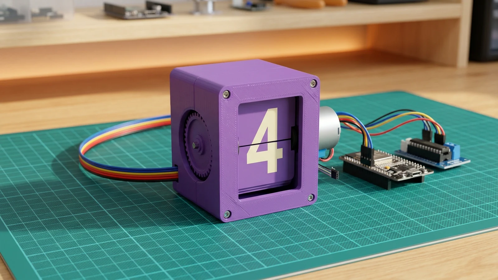
What you'll build
Build one working split-flap digit module: the mechanical unit that flips through numbers in a retro clock. The electronics are deliberately simple: an ESP32 sends four step signals to a ULN2003 driver, the driver moves a 28BYJ-48 geared stepper, and a KY-035 Hall sensor plus a small magnet gives the wheel a repeatable home position after boot.
Keep the first build to one digit. A split-flap clock only feels simple once one module can home reliably, move exactly one flap at a time, and recover after power loss. After that, duplicating the digit is mostly more drivers, more Hall inputs, and a clean power layout.
Watch the original build inspiration here on YouTube.
What you are building
This guide covers one numeric digit, not a complete multi-digit clock. The module has four jobs:
- spin the 28BYJ-48 through a ULN2003 driver,
- detect a known zero position with a magnet and Hall sensor,
- advance by a calibrated number of steps per flap,
- expose Serial Monitor commands so you can test digits before scaling up.
That boundary is intentional. If one digit misses steps, rubs mechanically, or homes unreliably, a four-digit clock will multiply the problem.
Upload and calibrate
Install the AccelStepper library, flash the starter sketch, and open Serial Monitor at 115200 baud.
Useful commands:
?prints available commands.rprints the current Hall sensor reading.hhomes the wheel using the magnet.0–9moves directly to a digit.nadvances to the next digit.dtoggles demo mode; manual digit commands automatically pause the demo cycle.
Start by sending r with the magnet away from the sensor, then again with the magnet near the sensor. Set HOME_THRESHOLD between those two readings. Most KY-035 boards read lower near the magnet; if yours reads higher, flip the comparison inside magnetDetected().
After homing works, send 0 through 9. If every move lands a little short or a little long, tune STEPS_PER_FLAP. The default 205 is a practical starting point for a 2048-step 28BYJ-48 and ten flaps, but printed tolerances and gear alignment can shift the real value.
Troubleshooting
- Motor buzzes but does not turn: check 5 V motor power, shared ground, and the coil order. The sketch uses
IN1, IN3, IN2, IN4, which matches many 28BYJ-48 + ULN2003 kits. - ESP32 resets during a move: use a separate 5 V supply for the motor and keep grounds common.
- Homing never finishes: print the Hall reading with
r, reduce the magnet gap, and tuneHOME_THRESHOLD. - Digit lands between flaps: adjust
STEPS_PER_FLAP, then test a full 0-9 cycle. - One flap works but later flaps drift: fix mechanical drag first, then lower speed or acceleration.
Scaling to a full clock
Once one digit is reliable, duplicate the motor driver and Hall sensor per digit. Keep motor power separate from ESP32 logic power, share grounds, and avoid reusing GPIO 34 for every Hall sensor; each digit needs its own input. A full clock also needs timekeeping logic, but the mechanical calibration should stay per digit.
Wiring diagram
Interactive · read-onlyPan and zoom to explore the wiring. Remix the project to edit it in your own workspace.
Parts list
Bill of materials| Component | Qty | Notes |
|---|---|---|
| ULN2003 stepper driver board | 1 | Driver board for the 28BYJ-48 geared stepper motor. It takes four ESP32 GPIO signals and switches the motor coils from a 5 V rail. |
| 28BYJ-48 stepper motor | 1 | Small 5 V geared stepper motor that advances the split-flap wheel. |
| KY-035 Hall effect sensor | 1 | Analog Hall sensor used with a 10 x 3 mm magnet to find the home position after boot. |
| 10 x 3 mm magnet | 1 | Small magnet fitted to the wheel so the Hall sensor can detect the home position. |
| 3D-printed split-flap digit module | 1 | Printed case, flap wheel, digit cards, shaft, gears, walls, inserts and screws for one mechanical digit unit. |
Assembly
4 stepsAssemble the printed flap wheel
Press the wheel parts onto the shaft, clamp the digit flaps in order, and fit the right-side cap and small gear. Use the M2 inserts and 8 mm M2 screws so the wheel stays square but can still rotate freely.
- Tip: Keep the flap cards in numeric order before closing the wheel.
- Tip: Turn the wheel by hand before adding the motor. Any scraping here will become missed steps later.
Mount the sensor and stepper
Install the KY-035 Hall sensor with the short M2 screws, then mount the 28BYJ-48 stepper motor with M3 screws. Place the 10 x 3 mm magnet so it passes close to the Hall sensor once per revolution.
- Tip: Leave a small air gap between magnet and sensor. It should trigger reliably without touching.
- Tip: Mark the home flap with tape during calibration so you can see when the code and mechanism agree.
- ⚠ Unplug power before adjusting the magnet near the sensor or motor wiring.
Wire the driver and Hall sensor
Connect ESP32 GPIO 16, 17, 18 and 19 to ULN2003 IN1-IN4. Power the ULN2003 motor side from 5 V, share GND with the ESP32, and connect the Hall sensor AO pin to GPIO 34 with VCC on 3V3.
- Tip: Use an external 5 V supply for the stepper if USB power sags or the motor chatters.
- Tip: GPIO 34 is input-only, which is fine for the analog Hall sensor.
- ⚠ Do not power the 28BYJ-48 directly from ESP32 GPIO pins. Use the ULN2003 driver board.
Upload and calibrate one digit
Upload the sketch, open Serial Monitor at 115200 baud, and let the wheel home against the Hall sensor. If the displayed digit lands between flaps, adjust STEPS_PER_FLAP slightly until each move centres the next number.
- Tip: Start with one digit unit before chaining multiple modules into a full clock.
- Tip: If homing never completes, print the raw analogRead(HALL_PIN) value and tune HOME_THRESHOLD.
Pin assignments
Board wiring reference| Pin | Connection | Type |
|---|---|---|
| GPIO 16 | uln2003-stepper-driver-1 IN1 | digital |
| GPIO 17 | uln2003-stepper-driver-1 IN2 | digital |
| GPIO 18 | uln2003-stepper-driver-1 IN3 | digital |
| GPIO 19 | uln2003-stepper-driver-1 IN4 | digital |
| 5V | uln2003-stepper-driver-1 5V | power |
| GND | uln2003-stepper-driver-1 GND | ground |
| 3V3 | ky-035-hall-sensor-1 VCC | power |
| GND | ky-035-hall-sensor-1 GND | ground |
| GPIO 34 | ky-035-hall-sensor-1 AO | analog |
Firmware
ESP32#include <Arduino.h>
#include <Stepper.h>
#define STEPS_PER_REV 2048
#define MOTOR_IN1 16
#define MOTOR_IN2 17
#define MOTOR_IN3 18
#define MOTOR_IN4 19
#define HALL_PIN 34
#define HOME_THRESHOLD 1800
#define FLAP_COUNT 10
#define STEPS_PER_FLAP 205
Stepper flapMotor(STEPS_PER_REV, MOTOR_IN1, MOTOR_IN3, MOTOR_IN2, MOTOR_IN4);
int currentDigit = 0;
bool magnetDetected() {
return analogRead(HALL_PIN) < HOME_THRESHOLD;
}
void stepForward(int steps) {
flapMotor.step(steps);
delay(80);
}
void homeWheel() {
Serial.println("Homing split-flap wheel...");
for (int i = 0; i < STEPS_PER_REV + 300; i += 4) {
if (magnetDetected()) {
currentDigit = 0;
Serial.println("Home magnet found");
return;
}
stepForward(4);
}
Serial.println("Home magnet not found. Check sensor alignment.");
}
void showDigit(int targetDigit) {
targetDigit = constrain(targetDigit, 0, FLAP_COUNT - 1);
int delta = (targetDigit - currentDigit + FLAP_COUNT) % FLAP_COUNT;
stepForward(delta * STEPS_PER_FLAP);
currentDigit = targetDigit;
Serial.printf("Showing digit %d\n", currentDigit);
}
void setup() {
Serial.begin(115200);
analogReadResolution(12);
pinMode(HALL_PIN, INPUT);
flapMotor.setSpeed(12);
delay(500);
homeWheel();
}
void loop() {
for (int digit = 0; digit < FLAP_COUNT; digit++) {
showDigit(digit);
delay(1200);
}
}“Deploy to device” opens this project in Schematik, where you can flash it to your board over USB.
Related builds
Remix this project
Make it yours in one click
Open a full copy of this project in your own Schematik workspace — diagram, code, parts, and assembly steps included. Swap the sensor, add features, or redesign the whole thing with AI. The author's original stays untouched.